Products
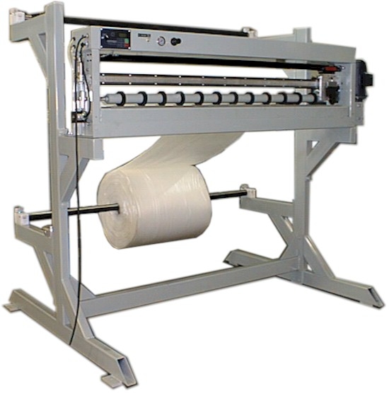
Omega Econno-Cutter
- Single or dual unwind – weight capacity up to 100 lbs
- Power Unwind – 500 lb. single or dual.
- Photo Eye – Pre-stages your next sheet.
- Pendant – 3 or 6 button
- Width sizes – 30”, 60”, 72”
- Easy set up and operation.
- Save time and labor cost.
- Free standing or overhead applications.
- Cuts clean with +/- 1/2 accuracy.
- Batch and length control, convenient foot pedal is standard.
Unwind Station
The basic function of the unwind station is to support a roll of material and provide web tension while the material is being unwound. Contech has many designs available to accommodate different material roll parameters. The weight, diameter, width and core diameter are all factors in specifying an unwind stand. The working elements and operation of the station are similar through all designs.
The 100 lb. unwind station provides a support system for rolls of material weighing up to 100 lb. The material is mounted to the unwind mandrel using tapered core inserts. The material is then routed into the EconoCutter.
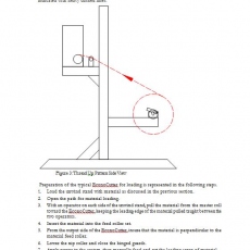
To load material onto the unwind mandrel press the blue button in the end of the retaining pin while pulling the pin. Open the hinged material support block and remove the shaft. Place the roll of material flat on the floor behind the unwind stand. Position the roll so that it will unwind from the top after being mounted. Place one core insert onto the shaft. Insert the shaft through the material core and place the second core insert on the shaft. Force the core inserts into the cores and tighten the setscrew. Lift the material roll onto the support blocks, close the hinged covers, and replace the pins.
Drive Roller
The Drive Roller is the roller that increments and measures the material. Roller position is provided to the control computer by an encoder attached to the Increment Drive Shaft. Acceleration, deceleration and, length information is calculated by the computer which, controls the DC drive card, powering the Increment Roller.
Cutter Blade
The Cutter Blade is the circular blade that travels the width of the machine, performing the cutting action.
The cutting system uses a pneumatic cylinder to provide blade movement. To perform a single cut, the pneumatic cylinder must travel the complete width of the machine. During the cut cycle, the blade is pushed from one end of the Cutter Head Support Tube to the other. An electrically activated 3-position 5-way pneumatic valve controls the direction of airflow into the cylinder. Located on the exhaust ports of the valve are adjustable flow mufflers that restrict the flow of air out of the cylinder. By restricting exhaust air of the cylinder, speed and force of the blade can be maintained throughout the entire cut cycle. Internally, a piston is forced back and fourth through the cylinder by airflow supplied by the control valve. Air is forced into opposite ends to move different directions. Limit Switches are mounted above the Cutter Head to provide position sensing. Two switches are used in the unit to provide end-of-travel limits for the actuator.
The coils are operated by 24VDC outputs supplied at the I/O board. The electric valve operates by moving an internal spool that redirects airflow. The spool operates in one of three positions: left, center, and right. When a coil is activated, the spool is pushed into position and airflow is directed to the cylinder expelling the return air from the cylinder and driving the cutting blade.
Nip Roller
The Nip Roller is a movable roller used to keep the material in contact with the Drive Roller. The roller may be placed into the open position, allowing more access for material loading.
Nip Roller Control
Nip roller control is provided by a lever, located in the operator end of the machine. The lever is attached to a shaft that spans the width of the machine, an eccentric cam is mounted to each end of the shaft, as the cam is rotated a gap is produced between the nip and drive rollers. Rotating the lever up will open the nip set; rotating the lever down will close the nip set. A flat spot in the cam provides a stopping point for the cam in the full open position. Nip pressure is provided by extension springs attached to pivoting lever arms located opposite the drive roller that applies pressure to the cam.
Static Eliminator
The static eliminator option will reduce the effects of electrostatic charges generated with some materials. The eliminator consists of two parts. The control box, mounted inside the right sheet metal cover, generates the high voltage source required to reduce the static charge. The second component is a Hot-Bar located under the front guard near the top cutting blade. An ON/OFF switch is located on the Static Eliminator power supply.
An alternate eliminator option uses a fan to blow ionized air. This may be adjusted to accommodate different materials. To adjust, locate the fan speed control on the right end of the static eliminator.
The static eliminator should only be activated when static becomes a problem. Vinyl and plastics are typical materials where static is generated. The Hot Bar style of eliminator must not be used on metallic materials.